|
|
| To
accomplish the goal of a rapid assessment conditions
survey, deterioration, as well as inherent physical
characteristics, such as wall height, wall thickness and number of
openings were vital for inclusion and for all of this data to be presented
spatially, mapping was necessary. Prior
to field work, time was spent creating baseline documentation. |
|
| The
initial goal for the project was to identify visible changes in the
adobe walls, as well as to identify possible causes for those changes,
based on comparison with previous NPS data. |
|
| Working
from existing HABS drawings and photographs, a new set of
drawings was created. This
included an expanded park wide site plan and elevations of the
exterior walls of the Mechanics Corral. It
also included a comprehensive base plan of the Mechanic’s Corral
incorporating all connected spatial data into a single geo-located
digital drawing file. |
|
 |
| While three
dimensional drawing systems such as
Building Information Modeling (BIM) have been making advances for
built cultural heritage; plans, sections and
elevations still remain the most accessible and common way of
conveying architectural ideas as well as providing an easily understood
usable format for any long term storage plan. For organizations such as
the National Park Service, there is very little clear evidence that BIM
data offers advantages. BIM requires specialized training and files saved in
formats that are not common to most parks and expensive specialized softwares can be a
significant burden to any park as a result of budget limitations, the
lack of readily available software training, and the limited duration
of many employees at a given park. Three dimensional drawings were
considered for the project, but using softwares such as AutoCAD, as
well as drawing conventions that were common and easily serviceable
(plan section and elevation) were seen as important considerations for
the long term storage and usage of these resources. In addition to the
obvious advantages of using this common simple solution, the complex
shapes of the walls made 3-D modeling far more difficult and would have
resulted in a significantly greater investment of time while
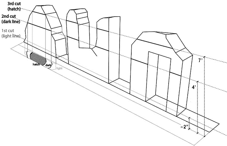
potentially offering little more in return. In fact the only use of
three dimensional drawing was for creating small graphic
displays that were
used to help explain how to read the plan view (see image below). |
|
| This allowed for spatial
representation of a wide range
of displays, both historic as well as conditional, to be created
either using AutoCAD or ArcGIS. For the new plan, it was understood
that a traditional approach to architectural drawing commonly found in
HABS work was not adequate to convey the complex relationship between
typical architectural features and the non-traditional aspects of
alteration, decay or loss. To understand phenomena such as decay
mechanisms for a site like the Mechanics Corral, it is critical that
relational information be provided contextually. Plan views
fundamentally offer built context by showing the walls of a structure
in
relation to each other, as well as in relation to cardinal orientation. |
 |
|
| They do
little, however, to express variation in wall heights or less
common aspects such as integrity of openings. Using a rigid
architectural framework towards plans, sections and elevations to convey
three dimensionality, often requires shifting between sheets to fully
grasp relationships. |
The new plan drawing required a more
significant amount of information about the walls. To create the
elevation drawings
ortho-rectified photographs were used (see image at top). Adobe
Photoshop and Agisoft
PhotoScan were used to create the rectified
photographic elevations. Since drawings and photographs don’t replace,
but instead complement each other, the rectified
photographs provided additional value beyond their
fuction as a foundation on which to build the drawing. While Photoshop
is a standard software found in most digital project software packages
Photoscan is not, and therefore requires time investment. Photoscan performs
photogrammetric processing of digital images generating 3D spatial data
by using the relationship between overlapping images. (Along with
exportable rectified photomontages, the software can integrate geocoded
data when available. During a different phase of the project, this was
used to create a 3-D mesh of the second
star fort with the aid of a UAV.)
The goal
with the newly developed plan was to
integrate variations in wall height traditionally
offered in elevations, but to do it in a way that it could be viewed
contextually in a plan.
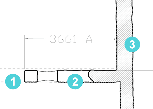
In order
to provide this more
comprehensive picture, additional information placed on the expanded
site plan included wall height as expressed as three sectional cuts,
each with its own graphic symbology. |
- The
adobe/foundation interface
- The
traditional height of walls in plan drawings (approximately 4 feet)
- Seven
feet above foundation which ensured that it exceeded the height
of both the tallest windows as well as the tops of all door
openings.
|
|
|
|
|
 |
|